Material Selection
All parts were printed on a Bambu Lab X1C with various materials and a 0.4 mm nozzle. Feel free to use other printers, materials and nozzles.
It is advisable to use some material that is not brittle. PLA+, PETG, ABS, or PA are possible choices. But we also manufactured robotic hands with TPU 98A, which increases the overall weight a bit, but also increases robustness. Though being a soft material, the links are still solid enough to provide a flawless operation.
When printing the fingertips with Filaflex 60A, don't use the automatic load and unload function. This will very easily damage the filament and the extruder won't be able to feed the filament any more. When in doubt, use Filaflex Foamy instead.
Naming Conventions

Bill of Materials
General Recommendations
Screws: We recommend using Torx flathead screws designed for plastic applications. These have the advantage of a low head profile while still providing a solid screwdriver interface. Please be aware that driving these screws into plastic parts needs to be done with prudence and without exerting too much force!
Note: In most cases, only two screws are used at each link. This offers the possibility to refasten parts, if the screws should have been over-tightended. Using metal screws in plastics parts can easily damage the plastic hole, and the screws won't secure any longer.
The motor blocks have covers with different thickness. Use the shortest screws that penetrate about 1-2 mm into the core motor element. When disassembling the fingers, the plastic can get damaged easily, and then you have some more possibility to actually use a longer screw to fasten the parts.
Before assembly, it is recommended to change the motor IDs and the basic communication settings. This can most easily be done with the Python script setMotorNumber.py in the Download section.
Preparations
- 3D print all links and fingertips.
- Each Dynamixel comes with a preconfigured cable. Cut six of them in half and add the corresponding receptable (JST EH).
- Program each Dynamixel with ID and baudrate, and label every motor.
Finger Assembly
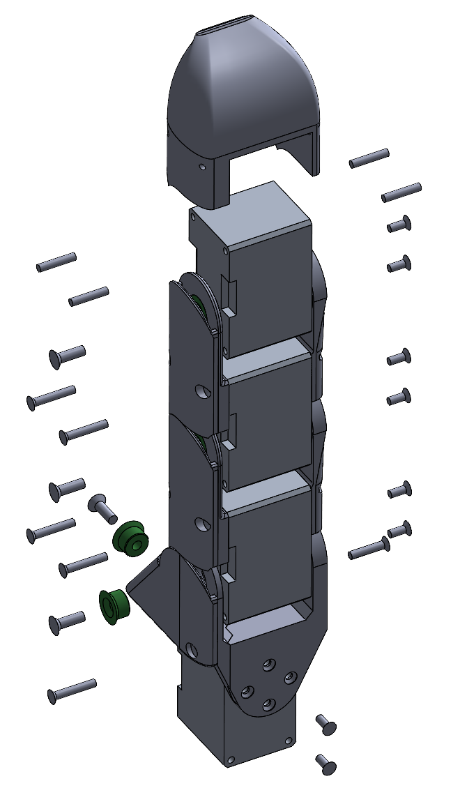
- Start with mounting the links on the motor horn side. This will give the finger its basic form and make the installation of the cabling easier. Use two 2.0x5mm screws for each motor horn, and two 2.0x10mm screws for connecting the adjacent motor.
Note: When fixing the link at the motor horn, make sure that the screws will not extend beyond the motor horn. This would block the motor horn movement!
When mounting the motor links, make sure that the horn is oriented in its zero position (one single mark facing towards the top). - On the opposite side, start with inserting two short cables into motor x2 (second phalanx), and guide them through the hole in the motor link. Carfully press the cables into position, so that the cable is tightly fixed below the link.
- Carefully fasten the link with the small joint adapter and a 2.5x8mm screw. Guide the palm-facing cable to the back-facing cable opening of the x1 motor.


- Guide the loose cable throught the hole of the next link part, and plug the cable in, again in the opposite facing cable header of the x3 motor.
- Insert a normal, long motor cable and feed it through the link hole as well. Plug into the back-facing header. Carfully press the cables into position, so that the cable is tightly fixed below the link.
- Carefully fasten the link with the small joint adapter and a 2.5x8mm screw.
- Apply the two cable covers and fasten them carfully with four 2.0x12 screws.
- Insert four set screws M2x10 in the x1 motor, so that the protrude a bit. Adjust the fingertip on top of it, while carfully inserting the motor cable.
- Mount the side motion link to both motor horns with 2.0x5 screws. Use the stronger XC330 motor in the x4 position.
- Mount the second part of the side motion link using the joint adapters, 2.5x8 screws, and fix the two parts with a 2.0x10 screw.
- Guide the long motor cable carfully around the back in the designated grooves and fasten with the cable cover. Fix the cable cover to the side motion link with a 2.0x12 screw.
- For the index and middle finger, add a short motor cable to the x4 motor. For the distal and thumb, us a normal, standard motor cable.
Note: The three normal normal fingers have an interlocking mechanism in the side motion link. This will restrikt movement, but allows to apply higher forces using a robot arm, for example. The thumb however needs more range of motion, so this side motion link has a slightly different geometry. Watch out to take the correct part for the tumb assembly.

Palm Assembly
- Add a short motor cable to the front-facing header of the motors 51 and a long, standard cable into 52.
- Push the plug and cable of motor 51 through the index palm part and push in the motor carefully. Make sure not to damage the cable. Fix the motor with two 2.0x10 screws from top and bottom.
- Repeat with motor 52 and the middle palm part.
- Carefully push the middle palm part onto the index palm part and fix it with two 2.0x6 screws.
- Insert the ball bearing and the screw adapter, and fix the M2.5x8 screw with the M2.5 nut.
- Repeat with the distal palm part.
- Carefully insert the thumb motor 24 into the adapter; make sure not to damage the motor cable when guiding it through the adapter. Fixate it with two 2.0x10 screws. Insert the adapter into the index palm part and fixate it with two 2.0x6 screws.
- Attach the three upper fingers with 12 2.0x10 screws.
- Plug the short motor cables of the index and middle fingers into the motors 51 and 52.
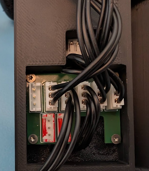
- Mount the motor distribution PCB onto the back of the thumb adapter. Plug in the motor cables of the four fingers, leaving an empty header in the middle for the external supply cable.